Custom CNC Machined Spline Shaft Manufacturer to Drawing
Custom CNC machined spline shafts built to your drawing or sample: involute, straight-sided and serration splines, DIN 5480 / ANSI B92.1 / ISO 4156, hardened and ground options, prototype to batch.
Custom CNC Machined Spline Shaft Manufacturer: Involute, Straight-Sided and Serrated Splines Built to Your Drawing
When an off-the-shelf spline shaft does not fit
Most transmission problems do not start with a broken shaft. They start with a shaft that was almost right: a spline that almost matched the coupling, a tolerance grade that was one level too loose, a material that hardened badly after heat treatment. “Almost” is enough to cause backlash, noise, fretting wear and, eventually, downtime on a machine that cannot afford it.
That is the situation a custom CNC machined spline shaft is made for. At [Company Name], we machine non-standard splined shafts for OEMs, gearbox builders and equipment manufacturers who cannot solve their drive problem with a catalog part. Send us a drawing, a worn sample, or even a sketch with the critical dimensions, and we will machine the spline shaft to fit the mating part, not the other way around.
This guide explains how we machine spline shafts, which spline types and standards we work to, what materials and heat treatments hold up in service, and what a buyer should check before releasing a spline shaft order.
What is a CNC machined spline shaft?
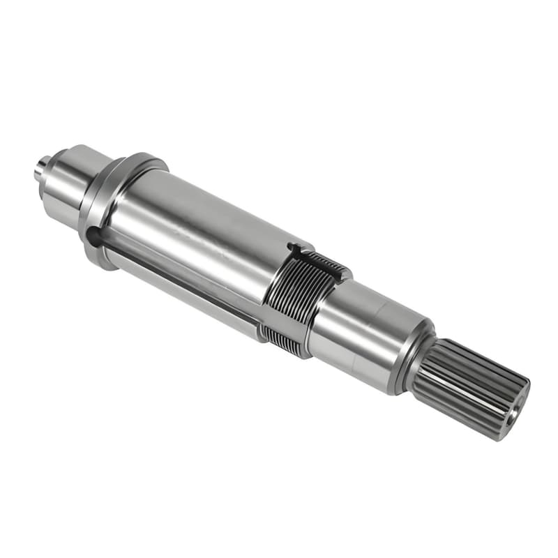
A spline shaft is a drive element with a series of equally spaced teeth, ridges or grooves cut along its length. The mating internal spline (in a hub, gear, coupling or sleeve) slides over it and transmits torque while staying concentric. Compared with a single keyway, a spline distributes load over many teeth, carries more torque for the same shaft diameter, and often allows the hub to slide axially while still driving, as in a gearbox synchronizer or a PTO driveline.
A CNC machined spline shaft is one whose blank, bearing journals and spline teeth are produced on CNC lathes, CNC milling machines, hobbing machines and (after hardening) cylindrical or form grinders, under numerical control rather than manual setup. That matters for custom work because the same equipment can switch from a 20-piece maintenance order to a 5,000-piece production run without rebuilding a dedicated line.
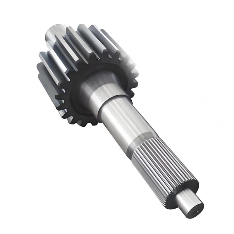
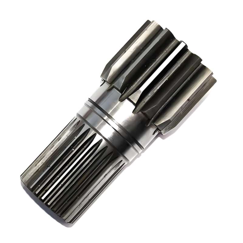
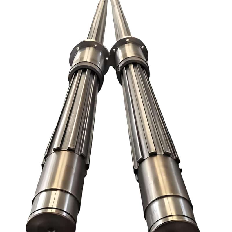
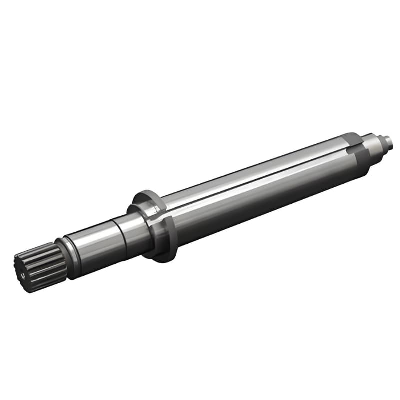
Spline types we machine
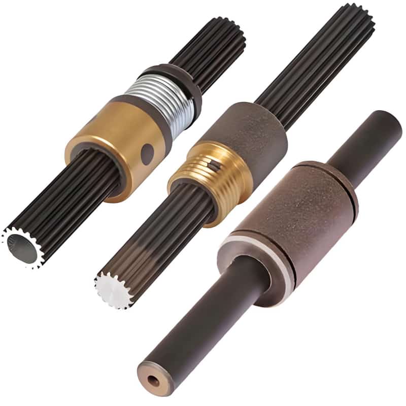
Buyers use the word “spline” loosely. The drawing usually points to one of four geometries, and the machining route changes with each one.
Involute spline shafts. The tooth flank is an involute curve, same family of geometry as a gear tooth. Involute splines self-center under load, distribute contact stress evenly and tolerate some misalignment. They are the default choice in modern gearboxes, planetary and cycloidal reducers, hydraulic pumps and automotive drives. We cut external involute splines by hobbing or CNC milling, finish them by form grinding when the drawing calls for hardened precision, and cut internal mating splines by shaping or broaching.
Straight-sided (parallel key) spline shafts. The teeth have flat, parallel flanks. Older machinery, agricultural equipment and some Eastern-European and Asian standard drivetrains still use them widely, often under DIN 5461–5464 or the corresponding national standards. Straight-sided splines are simple to inspect and straightforward to repair on legacy equipment, which keeps replacement demand steady.
Serrated spline shafts. Small, shallow triangular teeth at 37.5° or 45° pressure angle, typically used where a compact hub or lever must lock onto a shaft with no play: control linkages, steering columns, small couplings, hand levers. Serrations are often cold-formed in mass production, but for low-volume and replacement work we CNC mill or hob them.
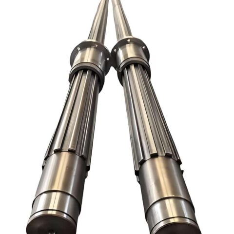
Helical spline shafts. Teeth follow a helix angle rather than the shaft axis, used where axial sliding must be smooth or where load transfer needs overlap between teeth at all times, such as certain machine-tool and marine drives. Helical splines are slower to machine and need careful setup, which is why many shops avoid them. We cut them on CNC hobbing and milling equipment with the helix set from the drawing.
We also machine internal splines, splined sleeves and spline couplings, because an external shaft is only half of a fit. When you order the mating pair from one shop, the backlash and fit class are matched on the same gear measuring equipment, and the two parts arrive guaranteed to assemble.
Standards and fit classes we work to
A spline is a matched pair, so the standard on the drawing decides everything: tooth geometry, fit class, inspection method and backlash. We routinely machine to:
- DIN 5480 – metric involute splines based on module, widely used in European gearboxes and industrial drives;
- ANSI B92.1 – inch-based involute splines, flat root and fillet root, common on North American equipment;
- ISO 4156 – metric straight cylindrical involute splines, with tolerance classes from 4 through 7;
- JIS B 1603 / D 2001 – Japanese industrial and automotive splines;
- DIN 5461–5464 / ISO 14 – straight-sided splines;
- Customer-specific and legacy drawings, including worn-sample reverse engineering where no drawing exists.
Three fit philosophies come up again and again: side fit (the flanks carry the load and centering), major-diameter fit (the outside diameter centers the hub), and minor-diameter fit. We will flag it if a drawing mixes fit conventions, for example a DIN 5480 spline dimensioned with ANSI-fit tolerances, because that mismatch is a common source of assemblies that bind or rattle.
How we machine a custom spline shaft, step by step
The process below is the route a typical hardened alloy-steel spline shaft takes through the shop. Soft stainless or prototype parts may skip hardening and grinding; high-volume parts may add broaching or cold rolling.
1. Drawing review and DFM feedback. Before any steel is cut, our engineer checks torque path, spline standard, fit class, radii at tooth roots, grinding allowance, heat treatment and how the spline relates to the bearing seats. If a sharp internal corner will harden into a crack starter, or the specified surface roughness cannot survive induction hardening, we say so at the quote stage and propose a fix, usually with a marked-up drawing.
2. Material selection and sawing. Bar stock is sawed to length with facing allowance. Every heat of alloy steel comes with mill material certificates; we can supply EN 10204 3.1 certificates on delivery.
3. CNC turning of the blank. We rough and finish-turn journals, shoulders, threads, seal seats and center holes on CNC lathes. The center holes become the datum for every later operation, so they are drilled and lapped carefully: spline runout to the bearing seats is usually the dimension that fails inspection on a badly made shaft, and it is decided here.
4. Spline cutting. The method depends on geometry, quantity and hardness plan:
- Hobbing for external involute and serration splines in medium and large batches, fast and consistent;
- Shaping for internal splines, shoulder-adjacent teeth and parts a hob cannot clear;
- Broaching for internal splines in stable batches;
- CNC milling (disk or end-mill form cutting) for one-offs, prototypes, helical splines and replacement parts where making a dedicated hob is not economic; this is usually how a “CNC machined spline shaft” from a sample is born.
5. Deburring and edge control. Tooth-end chamfers, lead-in bevels and burr removal are done by hand and by nylon wheel, never left for the customer to find at assembly.
6. Heat treatment. Chosen from the duty cycle, not from habit:
- Quench and temper (Q+T) for a tough 28–32 HRC core on 4140 / 42CrMo shafts;
- Induction hardening of the spline teeth to 50–58 HRC for wear resistance while keeping a tough core;
- Carburizing and quenching of 8620 / 20CrMnTi / 20CrMo for hard-teeth, soft-core gearbox shafts;
- Nitriding for low-distortion surface hardness on precision parts that cannot tolerate grind stock loss;
- Stress relieving where tight geometry and heavy machining would otherwise move the part after finishing.
7. Finish grinding. Bearing journals and seal seats are cylindrically ground to IT5–IT6. When the drawing requires a hardened precision spline, the teeth themselves are form-ground after heat treatment, which removes distortion and brings the spline to a clean fit class. This is the step that separates a shaft that runs quietly for years from one that howls at 3,000 rpm.
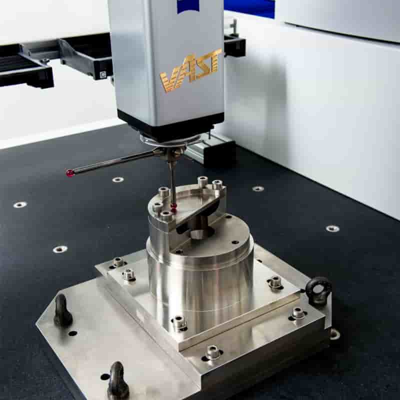
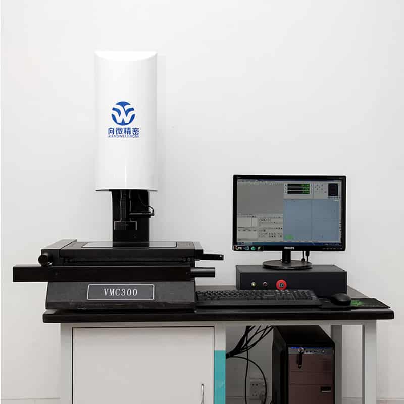
8. Inspection and documentation. Dimensional report, spline measurements (over-pins or over-balls M-dimension, tooth thickness, lead and profile where required), runout between spline and journals, surface roughness, hardness readings, and visual checks. Coordinate measuring and gear checking back up the functional GO / NO-GO spline gauges.
Materials we run
The spline geometry carries torque on paper. The material decides whether the shaft survives it.
| Material | Typical use |
|---|---|
| 4140 / 42CrMo4 (1.7225) | The workhorse for power transmission: Q+T core with induction-hardened spline teeth |
| 1045 / C45 | Light and medium duty, lower cost, limited hardenability on thick sections |
| 8620, 20CrMnTi, 20CrMo | Carburized gearbox shafts with hard teeth and a shock-resistant core |
| 304 / 316 / 303 stainless | Food, chemical, marine and washdown environments; 303 where machinability dominates |
| 17-4 PH, nitronic grades | High-strength corrosion-resistant drives |
| 6061 / 7075 aluminum, brass C36000 | Light-load instrument, fixture and consumer-equipment splines |
| Customer-specified grades | ASTM, EN, JIS equivalents cross-checked against your drawing before cutting |
If you are unsure between 4140 and 8620, the short version: 4140 with induction-hardened teeth is the economical answer for steady loads; carburized 8620-family steel is the safer answer for shock loads, reversals and high tooth-contact stress. We will recommend based on the torque and duty cycle you describe.
Capabilities at a glance
- Shaft diameter range: roughly 8 mm to 300 mm, lengths to around 1,500 mm (confirm with engineering for long, slender shafts)
- Spline modules from ~0.5 to 8; diametral pitches from ~2.5 to 48
- Diametral accuracy to IT6 on ground surfaces, IT7 on as-cut splines
- Concentricity / runout between spline and bearing seats down to 0.01–0.02 mm
- Surface roughness to Ra 0.8 on ground journals, Ra 1.6 typical on tooth flanks
- One-off prototypes, spare-part reverse engineering, and batch production on the same line
- Secondary operations: keyways, cross holes, retaining-ring grooves, threads, black oxide, zinc/nickel plating, phosphating, nitriding, passivation for stainless
Where custom splined shafts end up
We make CNC machined spline shafts for any driveline where rotation has to transfer through a removable or sliding hub:
- Gearboxes and speed reducers – planetary, cycloidal, worm and helical gearbox input/output shafts, pinion shafts with integrated splines
- Agricultural machinery – PTO shafts, clutch shafts, feeder and auger drives
- Construction and mining equipment – pump drive shafts, motor shafts, swing and travel drives
- Automotive and trucks – transmission shafts, transfer case shafts, steering and differential components
- Hydraulic pumps and motors – pump rotor shafts where the spline runs in oil and must resist fretting
- Machine tools and automation – spindle and feed shafts, sliding drive sleeves
- Marine, food and chemical equipment – stainless spline shafts for corrosive or washdown settings
- Maintenance and repair – replacement spline shafts for obsolete machines whose OEM stopped supplying parts
Why buyers send spline shaft work to [Company Name]
We are set up for non-standard work. Standard shaft factories want a repeatable part number in five-figure quantities. Our equipment and quoting process are built around the opposite: mixed drawings, low volumes, unusual standards and parts that exist only as a worn sample.
We read the drawing like an engineer, not like a typist. Roughly a third of spline inquiries carry a small internal conflict: fit class vs backlash, material vs heat treatment, spline length vs hub travel. Catching these before cutting steel is cheaper for everyone, and our quotes routinely come back with questions or a DFM note instead of a silent guess.
Reverse engineering from a sample is routine. When the original drawing is gone, we measure the worn shaft, identify the standard and module, design for the mating hub rather than the worn tooth thickness, and deliver a usable replacement plus a new drawing for your records.
Matched pairs stay under one roof. Ordering the external spline shaft and internal spline sleeve or coupling together means one fit calculation, one inspection standard, and no finger-pointing if a tolerance stack does not close.
Documentation for regulated buyers. Mill certs, EN 10204 3.1 material certificates, dimensional and first-article inspection reports, hardness and roughness records, and third-party inspection (SGS, BV or your nominated inspector) can be arranged before shipment.
Lead times built for maintenance emergencies. Prototypes and one-off replacement shafts are treated as priority work because a stopped production line does not wait for a standard production slot. Share the deadline with the RFQ and we will tell you honestly what is achievable.
How to request a quote
The faster the information arrives, the faster the quote. Ideally send:
- A 2D PDF drawing with tolerances, spline standard/fit class, material, heat treatment and surface finish;
- A 3D model in STEP, IGES or X_T if available;
- Quantity (prototype, first batch, annual volume);
- The mating part details or the internal spline drawing if you want a matched pair;
- Any required certificates or inspection level.
No finished drawing? Send the failed shaft, photos with dimensions, or a hand sketch of the critical interfaces. We will close the gaps with you by email or a short call. Quotes usually go out within 24 working hours.
Frequently asked questions
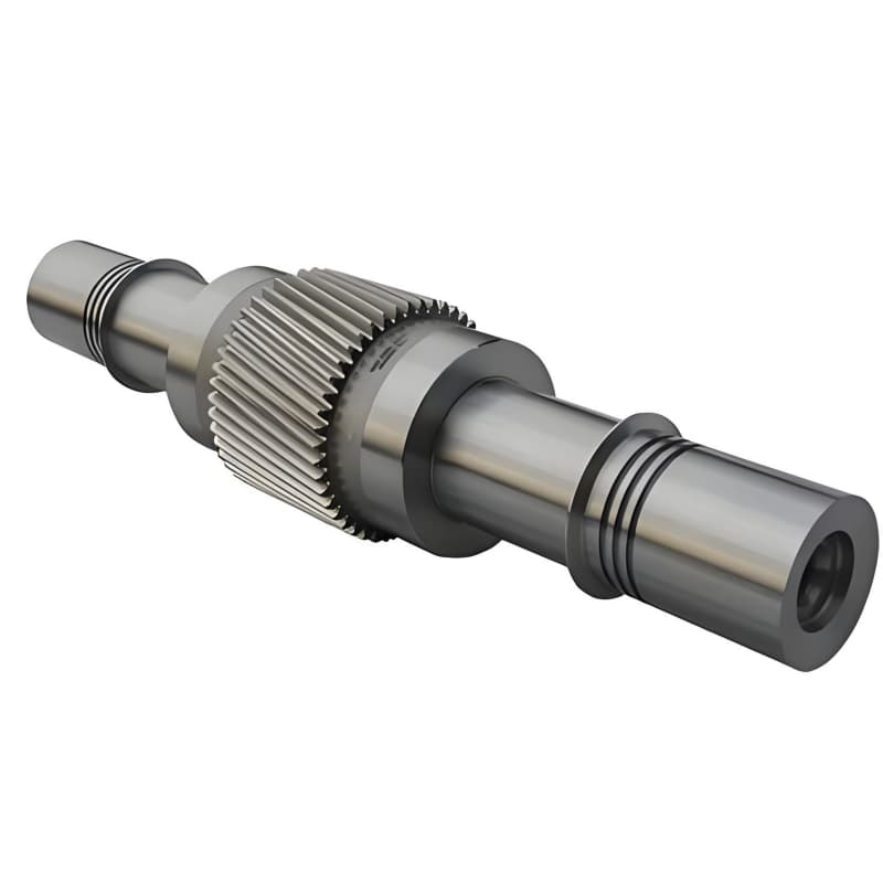
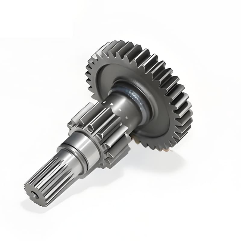
What is the difference between a spline shaft and a gear shaft? A gear shaft meshes with a separate gear to change speed or torque, and its teeth are sized for that mesh. A spline shaft mates with an internal spline in a hub or coupling mainly to transfer torque along the same axis, often while letting the hub slide. Many shafts combine both: gear teeth in one section, spline teeth in another, and we machine those integrated parts regularly.
Involute or straight-sided splines, which should I choose for a new design? For a clean-sheet design, involute splines (DIN 5480, ANSI B92.1 or ISO 4156) are usually the better call: stronger teeth for the same size, self-centering contact, and broader tooling support. Choose straight-sided splines when you must match existing legacy hardware, an industry standard forces it, or the maintenance team needs simple flat-flank geometry.
Can you machine a spline shaft from a sample without a drawing? Yes. We measure the sample, determine the spline standard, module or pitch, pressure angle and fit, account for wear on the original teeth, and machine a replacement that fits the mating hub. A new drawing is delivered with the part so the next replacement is a drawing order, not another reverse-engineering job.
How precise is a CNC machined spline shaft? As-cut hobbed or milled splines typically hold IT7–IT8; form-ground splines after hardening reach IT6 and tighter, with runout between the spline axis and bearing journals at 0.01–0.02 mm. The right target depends on the application: a hand-lever serration does not need gearbox-grade grinding, and we will not sell you grinding it does not need.
Which heat treatment should a spline shaft have? General industrial drives usually use 4140/42CrMo quench-and-temper with induction-hardened spline teeth. Heavy shock-loaded gearbox shafts use carburized 8620-family steel. Parts that cannot tolerate heat-treatment distortion use nitriding. Tell us the torque, speed, reversals and expected life, and we will recommend a treatment instead of leaving the box blank on the drawing.
What minimum order quantity do you accept? One piece. Prototypes, single replacement shafts and maintenance spares are normal work here, alongside repeat batches. Unit price drops with quantity, but there is no MOQ gate that forces you to over-order a non-standard part.
How long does a custom spline shaft take? A simple turned-and-milled prototype can ship in days; a hardened and ground matched pair with inspection reports typically takes a few weeks. Exact timing comes with the quote, and rush maintenance orders can be fast-tracked if you flag the downtime situation up front.
Do you ship to North America, Europe, Russia, South Africa or Pakistan? Yes. We export custom machined parts worldwide under agreed Incoterms (FOB, CIF, DAP or your nominated forwarder), with export packing suited to long shafts and full shipping documents.
Send us the spline that is giving you trouble
If your current shaft works on paper but binds, wears or whines in the machine, the problem is usually in fit class, heat treatment or datum strategy, and it is fixable. Send your drawing or sample to [Company Name] for a free engineering review and a quote within 24 working hours. Whether you need one replacement CNC machined spline shaft to restart a stopped line, or a batch run of involute spline gear shafts for a new gearbox program, the same team handles it from first cut to final inspection report.
More custom CNC turning service according to your drawings
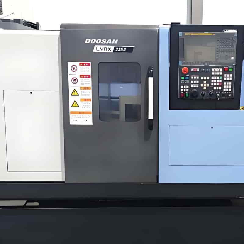
CNC turned 4140 alloy steel parts to customer’s drawing