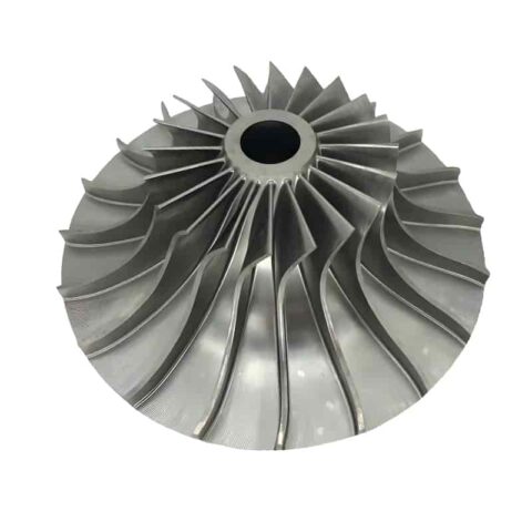
5-Axis CNC Machined Impellers Exactly to Drawings
Custom 5-axis CNC machined impellers built to your drawings. Aluminum, titanium, stainless & Inconel. Dynamic balancing,
5-Axis CNC Machined Impellers: Custom High-Performance Impellers Built Exactly to Your Drawings
An impeller is the rotating heart of every centrifugal pump, compressor, blower, turbocharger, and turbine — its curved blades transfer energy to a fluid (liquid, gas, or air) and directly determine flow rate, pressure ratio, efficiency, noise level, and service life.
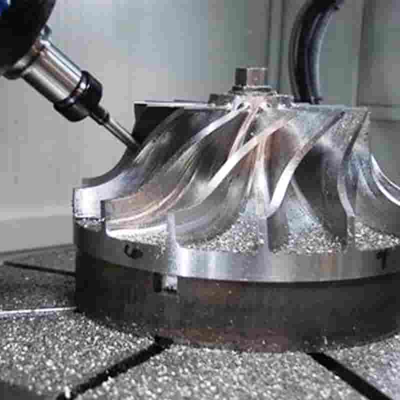
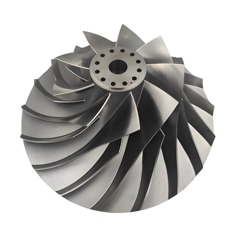
A 5-axis CNC machined impeller is milled from a single solid billet on a simultaneous 5-axis machining center, rather than cast, welded, or assembled from separate blades. Because the cutting tool reaches the workpiece from five controlled axes at once (X, Y, Z plus two rotational axes), even deeply twisted, tightly spaced, undercut blades can be machined in one single setup, with continuous tool contact along the entire blade surface.
As a non-standard custom machining manufacturer, we produce impellers strictly according to customer drawings, 3D models, and performance requirements — no catalog parts, no “close enough” standards. Whether you need one prototype for R&D testing, a small batch for field trials, or serial production for an assembly line, every impeller is engineered and machined around your geometry, your material, and your application.
Why 5-Axis Machining Is the Only Right Choice for Impellers
Impeller geometry is among the most difficult in all of precision machining: blades are three-dimensionally twisted, the gap between adjacent blades narrows toward the hub, and the blade surfaces often cannot be reached by a 3-axis tool without collision. 5-axis simultaneous machining solves these problems at their root.
| Challenge | How 5-Axis CNC Solves It |
|---|---|
| Twisted, swept blade surfaces | Tool orientation follows the blade surface continuously (flowline / swarf milling), producing a smooth, accurate airfoil |
| Narrow channels between blades | Short, rigid tools reach deep pockets without holder collision, thanks to automatic tilt control |
| Undercuts and shrouded (closed) impellers | Rotary axes expose hidden geometry in one clamping — no second fixturing, no mismatch |
| Tight dynamic balance requirements | One-setup machining keeps concentricity between bore, hub, and blade stack within microns |
| Thin blade deflection | Shorter tool overhang + high-speed finishing reduces cutting forces and blade vibration |
| Repeatability across batches | Proven CAM programs and in-machine probing deliver identical parts run after run |
The result: better aerodynamic/hydrodynamic efficiency, smoother surface flow, lower risk of crack initiation, and an impeller that matches the designer’s CFD model — not an approximation of it.
5-Axis vs. Casting vs. 3-Axis: A Quick Comparison
- Casting carries porosity, draft angles, long mold lead times, and poor surface integrity — unacceptable for high-speed or high-purity applications.
- 3-axis machining requires multiple setups, leaves witness lines at re-fixturing joints, and often cannot reach between closely spaced blades at all.
- 5-axis CNC from solid stock delivers full density (no porosity), no mold cost, design-change flexibility, superior surface finish, and lead times measured in days — ideal for prototypes, performance parts, and low-to-medium volume production.
Impeller Types We Manufacture
We machine every impeller configuration used across rotating-equipment industries:
- Open impellers – blades exposed on one side; easy to machine, tolerant of contaminated fluids.
- Semi-open impellers – blades with a back shroud/wear plate; common in high-pressure pumps and compressors.
- Closed (shrouded) impellers – full front and rear shrouds; highest efficiency, machined with advanced 5-axis toolpaths or split-then-weld/braze routes per drawing.
- Centrifugal / radial impellers – radial outflow for pumps, blowers, and compressors.
- Mixed-flow impellers – combined axial/radial flow for high flow + medium head.
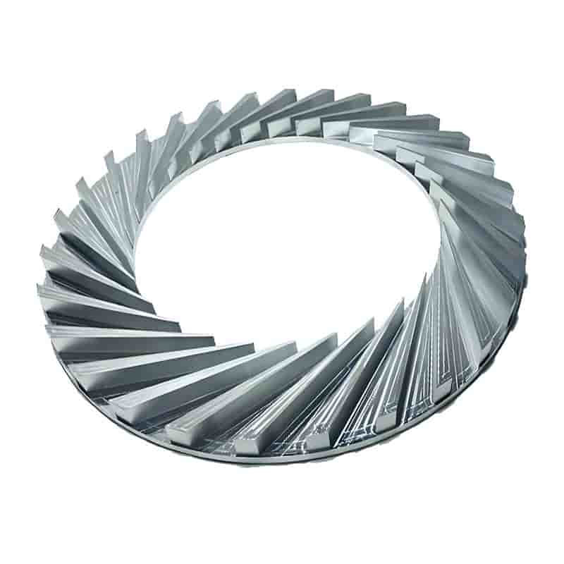
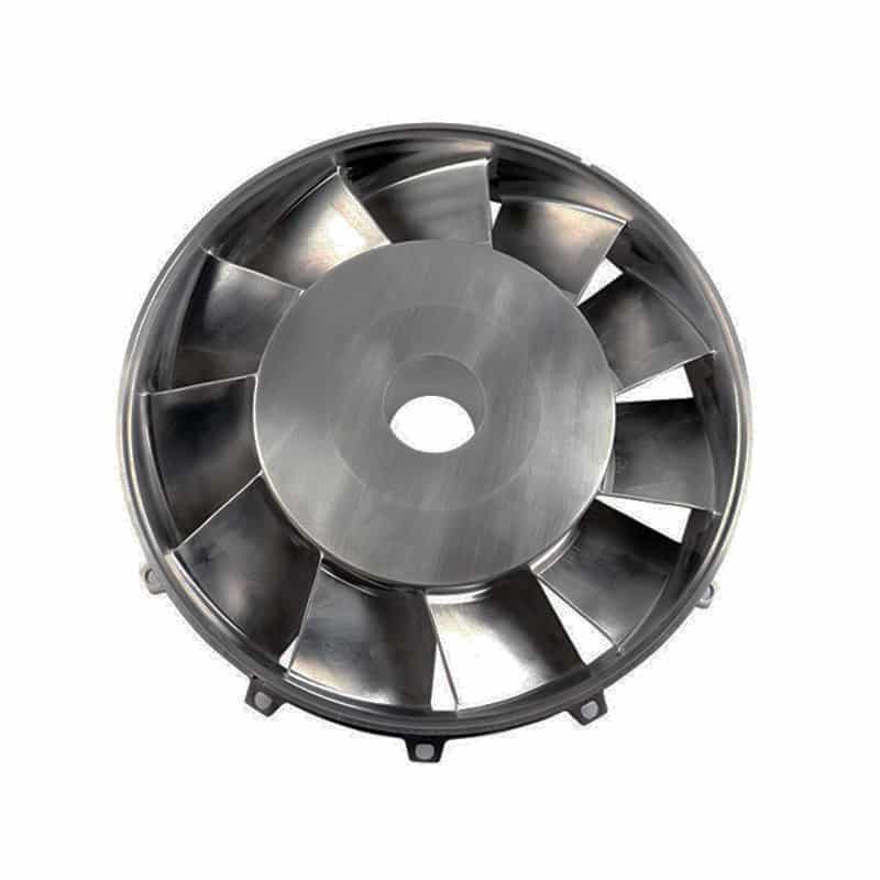
- Axial-flow impeller rotors / inducer blades – helical blades for inducers and axial fans.
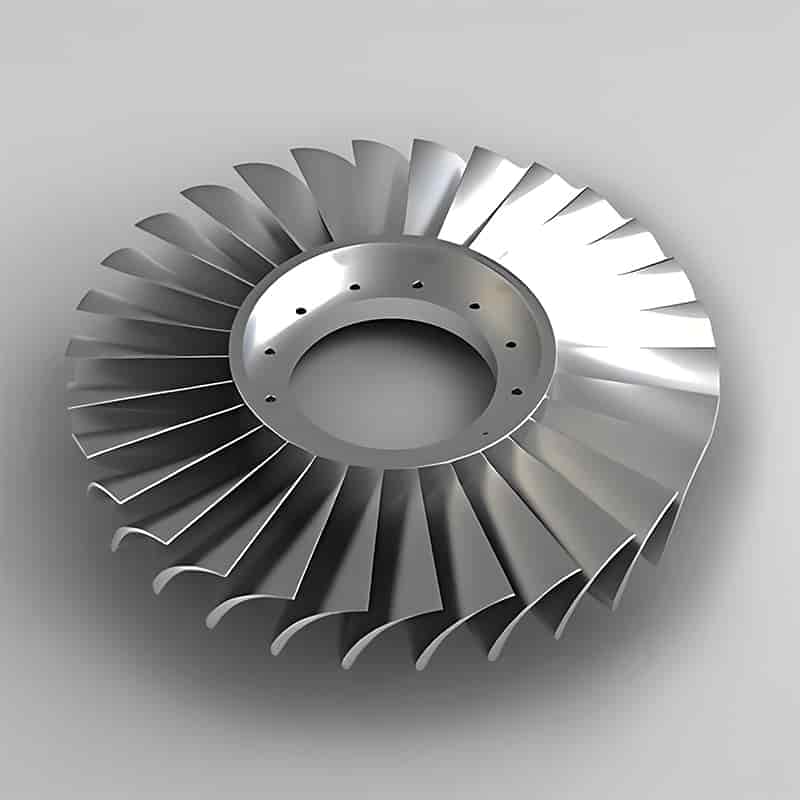
- Turbocharger compressor wheels & turbine wheels – high-RPM, high-temperature alloy wheels.
- Tandem-bladed / splitter impellers – alternating long and short blades to extend stable operating range.
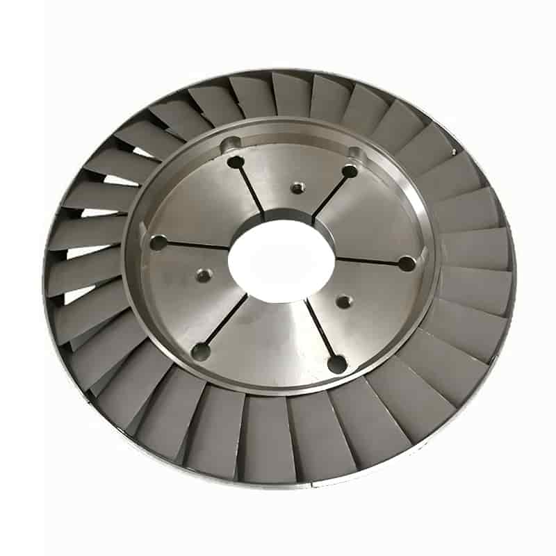
- Blisks (bladed disks) and fan rotors – integrally bladed disks for aerospace and ventilation.
Both forward-curved, backward-curved, and radial-tip blade profiles are produced directly from your STEP/IGES/X_T model.
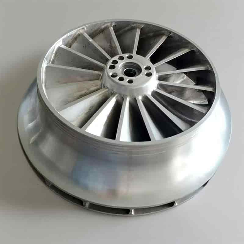
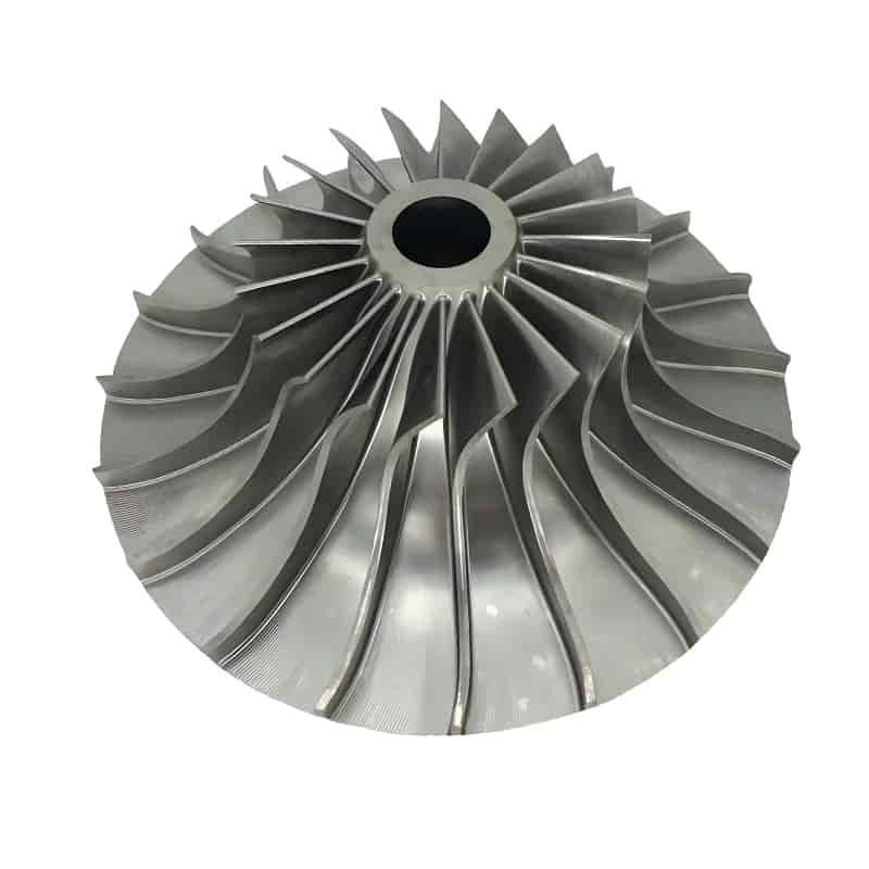
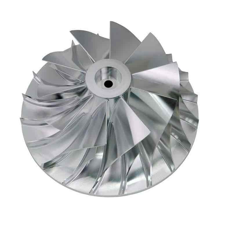
Materials We Machine for Custom Impellers
Material choice is driven by rotational speed, fluid chemistry, temperature, and weight targets. We routinely machine:
表格
| Material | Typical Grades | Common Applications |
|---|---|---|
| Aluminum alloy | 6061-T6, 7075-T6, 2A12, 2024, A356 forged | Compressor wheels, blowers, low-temp fans — light and easy to balance |
| Stainless steel | 304, 316L, 17-4 PH, 15-5 PH, 2205 duplex | Chemical pumps, food-grade pumps, seawater, corrosion resistance |
| Titanium | TC4 / Ti-6Al-4V, Grade 2, Grade 5 | Aerospace, turbochargers, medical, high strength-to-weight |
| Nickel superalloy | Inconel 718, Inconel 625, Hastelloy C276 | Turbines, exhaust-side wheels, extreme heat & corrosion |
| Copper / brass / bronze | C36000, tin bronze, beryllium copper | Marine pumps, conductive/antimicrobial environments |
| Tool & alloy steel | 4140, 4340, SKD11, H13 (hardened) | High-load industrial rotors |
| Engineering plastics | PEEK, PPS, PVDF, UHMWPE, Delrin | Chemical, semiconductor, lightweight non-sparking fans |
All stock is sourced with material certificates (EN 10204 3.1 mill certs) on request, and every billet is inspected before cutting.
Our 5-Axis Impeller Manufacturing Process — Step by Step
Transparency matters in custom work. Here is exactly how a drawing becomes a finished impeller on our floor.
Step 1 – Drawing & DFM Review (within 24 hours) Our engineers review your 2D drawing (PDF/DWG) and 3D model (STEP/IGES/X_T), checking blade-wall thickness, fillet radii, tool reachability, bore/datum scheme, and balancing stock. We return a free DFM report flagging any geometry that should be adjusted before metal is cut — saving you a failed prototype.
Step 2 – Material Sourcing & Certification Billet cut from certified bar/forging; raw material hardness and dimensions verified; certs archived to your lot number.
Step 3 – CNC Turning (Lathe) Turn the outer diameter, hub faces, central bore, seal steps, and threading, establishing the rotational datums that all later operations reference.
Step 4 – 5-Axis Roughing Adaptive high-efficiency roughing removes up to 90% of channel stock with controlled tool load, leaving uniform semi-finish allowance — critical to avoid blade deflection from uneven residual stress.
Step 5 – Stress Relief (when specified) For thin blades, titanium, or superalloys, an intermediate stress-relief / normalization cycle prevents post-machining distortion.
Step 6 – 5-Axis Simultaneous Semi-Finishing & Finishing
- Flowline (surface) finishing along blade iso-parametric lines for a continuous, flow-friendly surface;
- Swarf (flank) milling where ruled blade surfaces permit;
- Point milling for free-form splitter blades;
- Separate hub, blade pressure side, and suction side toolpaths with overlap-free finishing;
- Ball/barrel cutters down to R0.3 for narrow channels.
Step 7 – Deburring & Edge Preparation Hand + mechanical deburring under magnification; controlled leading/trailing edge radii exactly per drawing (edge condition is decisive for efficiency and fatigue life).
Step 8 – Surface Treatment & Coating (optional) Anodizing (aluminum, any color), hard anodizing, passivation (stainless), electropolishing, nickel/PTFE coating, black oxide, sandblasting, polishing, or specialized PTFE/MoS₂/ceramic coatings to reduce fouling.
Step 9 – Dynamic Balancing Single- or two-plane dynamic balancing to G2.5 / G1.0 grade (ISO 1940-1) at your design RPM, with material removed only from designated balance lands.
Step 10 – Final QC & Packaging CMM dimensional report, surface roughness records, balancing certificate, anti-corrosion packaging with foam-separated layers for export shipment.
Precision, Tolerances & Surface Finish We Hold
| Parameter | Standard Capability | Tighter on Request |
|---|---|---|
| General tolerance | ISO 2768-m / ANSI B4.3 | IT5–IT6 critical features |
| Blade profile accuracy vs. 3D model | ±0.03–0.05 mm | ±0.015 mm with on-machine probing |
| Bore diameter tolerance | H7 | H5 / H6 |
| Concentricity / runout (bore to OD) | ≤ 0.01 mm | ≤ 0.005 mm |
| Blade thickness consistency | ±0.02 mm | ±0.01 mm |
| Surface roughness | Ra 1.6–3.2 μm as-machined | Ra 0.8 / Ra 0.4 mirror polish |
| Impeller outer diameter range | Ø10 mm – Ø800 mm | Larger by discussion |
| Batch size | 1 piece prototype – 10,000+ pcs/year | Kanban / blanket orders |
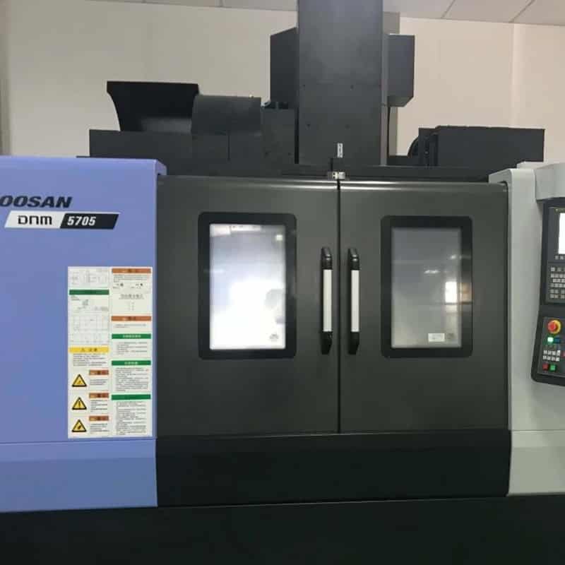
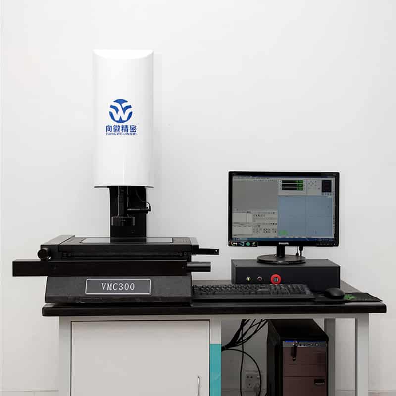
Equipment includes simultaneous 5-axis centers (table-table and head-table configurations), 3/4-axis CNC mills, CNC lathes with live tooling, CMM (three-coordinate measuring machine), optical profile projector, roughness tester, and dynamic balancing machines.
Industries Served
Custom 5-axis impellers from our shop operate in:
- Aerospace & defense – compressor rotors, APU wheels, cooling-air fans, UAV turbofan components;
- Automotive & motorsport – turbocharger compressor wheels, intercooler fans, supercharger rotors;
- Pumps & fluid handling – centrifugal, multistage, submersible, magnetic-drive, and cryogenic pumps;
- Oil, gas & energy – Inconel turbine wheels, gas-metering rotors, fuel-cell air compressors;
- Marine – seawater pump impellers in duplex stainless and bronze;
- HVAC & industrial blowers – high-efficiency backward-curved fan wheels;
- Medical & semiconductor – PEEK/PPS clean-fluid impellers, vacuum pump rotors;
- Food, pharma & chemical – 316L electropolished impellers meeting sanitary geometry;
- Rail, e-mobility & electronics cooling – high-speed motor cooling fans.
Quality Assurance: How We Prove Every Impeller Is Correct
For rotating parts at 20,000–200,000 RPM, “looks good” is not a quality method. Our documented QA system covers:
- Incoming inspection – alloy grade verification (XRF spectrometer available), hardness, cert matching;
- In-process control – first-article inspection (FAI) per AS9102/PPAP style, in-machine probing after roughing;
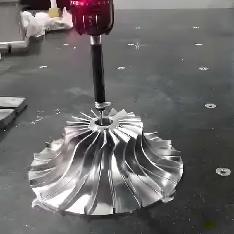
- Full dimensional inspection – CMM scan of blade sections against the nominal 3D model, with color-mapped deviation reports;
- Surface verification – calibrated roughness tester, visual inspection under controlled lighting;
- NDT on request – dye penetrant inspection (DPI), ultrasonic or X-ray for critical wheels;
- Dynamic balancing report – residual unbalance in g·mm, correction grade, and test RPM;
- Traceability – every shipment carries lot number, material heat number, inspection report, and (on request) material/processing certificates.
Why Buy Your Custom Impellers From Us
- True non-standard focus. We do not sell catalog impellers — every order is built to your drawing. Reverse engineering from a worn sample or a point cloud is also supported.
- 5-axis in-house, not brokered. Direct control over programming, fixturing, and finishing means shorter lead time and accountable quality.
- Design-confidentiality friendly. NDA signing before model exchange; your CFD geometry never leaves controlled folders.
- Prototype-to-production continuity. The same CAM program, fixtures, and inspection plan carry from your first test wheel to series delivery — no re-qualification surprises.
- Export-experienced communication. English engineering correspondence, clear DFM feedback, incoterms-aware logistics (FOB/CIF/DDP by discussion), and packaging validated for air/sea freight.
- One-stop finishing. Machining, balancing, anodizing/plating/coating, laser marking, and assembly-ready packaging under one PO.
- Flexible MOQ. One prototype is accepted; small-batch iteration is welcomed — exactly how R&D projects actually work.
What We Need to Quote Your Impeller in 24 Hours
To return an accurate price, lead time, and DFM note, please send:
- 3D model – STEP / IGES / X_T / SolidWorks (required for blade surfaces);
- 2D drawing – PDF/DWG with bore tolerance, datum structure, edge radii, surface roughness, and critical notes;
- Material & grade, or the operating conditions (fluid, temperature, RPM) if you want our recommendation;
- Quantity – prototype quantity and expected annual volume;
- Required certificates / inspections – material cert, balancing grade, CMM report, NDT, etc.;
- Surface treatment / coating requirements;
- Target delivery date and destination port.
No drawing yet? We can also work from a worn physical sample (reverse engineering), a sketch with performance targets, or an existing impeller you want improved.
Frequently Asked Questions
Q1: Can you machine a closed/shrouded impeller completely from one piece? Yes, where internal channels are tool-accessible we machine closed impellers integrally on 5-axis centers. For geometry beyond tool reach, we produce split halves and weld/braze them per drawing, followed by stress relief and full inspection — the route is always agreed with you in the DFM stage.
Q2: What is your typical lead time? Prototype aluminum impellers commonly ship in 7–15 working days after drawing approval; stainless/titanium/superalloy parts and batches take 15–30 days depending on heat treatment and coating. Rush service is available for urgent R&D schedules.
Q3: How thin can the blades be? We routinely finish aluminum blades down to 0.4–0.6 mm and steel/titanium blades down to ~0.8–1.0 mm, depending on blade height and material. Exact limits are confirmed by DFM against your model.
Q4: Can you match an existing impeller without a drawing? Yes. Send the physical part or a 3D scan; we reconstruct the blade surfaces, draw a full model for your approval, then machine — useful for obsolete pump spares and performance upgrades.
Q5: Which file format do you prefer? STEP (.stp) is preferred for the 3D model plus a PDF of the dimensioned drawing. Native SolidWorks, Inventor, X_T, and IGES are all accepted.
Q6: Do you sign NDAs? Absolutely. Mutual or one-way NDAs are signed before any model exchange on request.
Q7: What is your MOQ? One piece. Custom work starts at a single prototype, and pricing steps down at 5, 10, 50, and series quantities.
Request a Quote Today
If your equipment demands an impeller that performs exactly as the CFD model predicts — with verified blade geometry, certified material, documented balancing, and a supplier who actually reads your drawing notes — send us your 3D model and 2D drawing now. Our engineering team will reply within 24 hours with a detailed quotation, a DFM review, and a realistic production schedule.
Custom 5-axis CNC machined impellers — made to your drawing, built to perform, delivered to your factory door.