Custom CNC Machining for Robotics and Humanoid Robot Components
We manufacture custom CNC machined robotics and humanoid robot components — aluminum, titanium and stainless precision parts, 5-axis milling and turn-mill, from one-off prototypes to low-volume production, with CMM reports and full material traceability.
Custom CNC Machining for Robotics and Humanoid Robot Components
1. Why robotics teams rely on custom CNC machining instead of catalog parts
A humanoid robot is essentially a dense stack of actuators, sensors, and load-bearing structure packed into the smallest possible envelope. Every gram added to an arm or a leg changes the torque the joint motor must deliver, the heat it generates, and the battery life of the whole machine. Every tenth of a millimeter of play in a joint bore shows up as positioning error at the robot’s hand or foot.
That is why off-the-shelf brackets, flanges, and standoffs rarely survive past the first prototype of a serious robotics program. Catalog parts are built to unknown material tempers and loose tolerances, and their geometry is fixed. Custom CNC machining gives a robotics design team three things no standard part can:
- Controlled material. You specify the exact alloy and temper — 7075-T6 aluminum, Ti-6Al-4V titanium, 17-4 PH stainless, PEEK — and receive material certificates with the parts.
- Controlled geometry. Bores, bolt circles, locating faces, and shaft seats are machined to the drawing, with GD&T callouts met and documented.
- Controlled iteration. When the design moves from revision A to revision D, the same shop cuts the new version against retained programs and setup notes, so changes stay predictable.
We are a non-standard, build-to-print machine shop: we do not sell a catalog. Every robotic component and every humanoid robot component we ship is made from a customer’s 3D model and drawing. This article explains what that actually covers, what tolerances and materials are realistic, and how to source CNC machined robot parts without surprises.
2. The robotics and humanoid robot components we machine most often
Most humanoid robot hardware falls into four families: actuation, structure, sensing, and end-effector parts. The list below reflects the parts that cross our machines week after week for robotics customers.
| Component family | Typical parts | Process | Common materials | Typical precision |
|---|---|---|---|---|
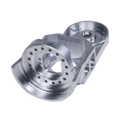
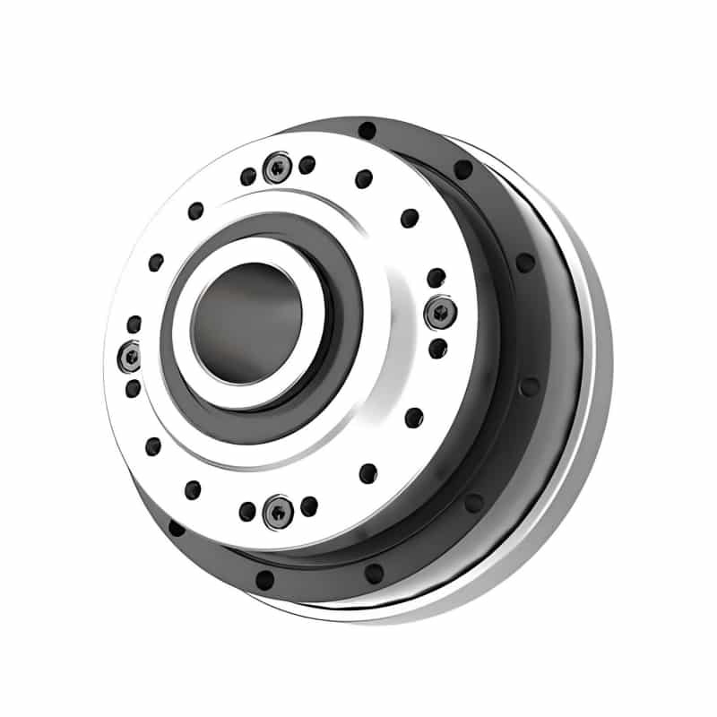
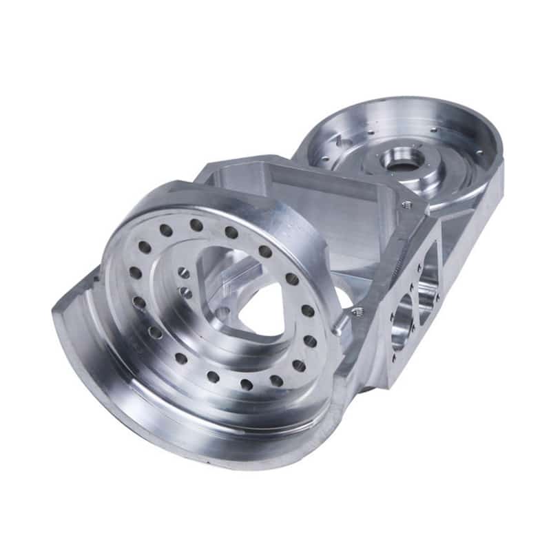
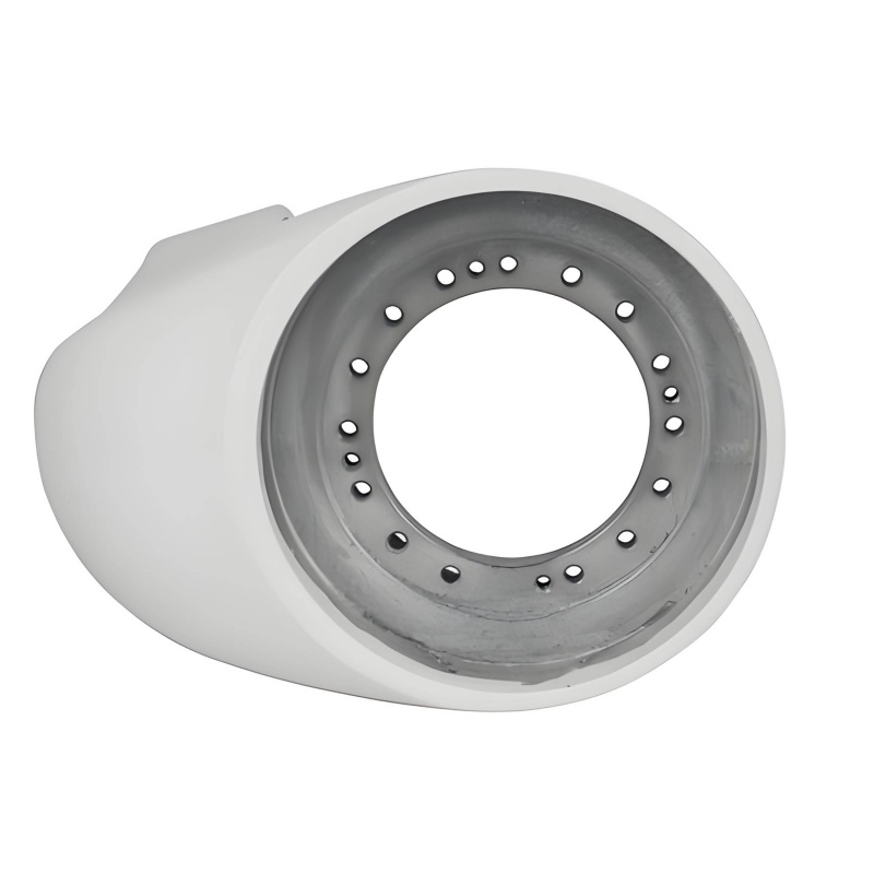
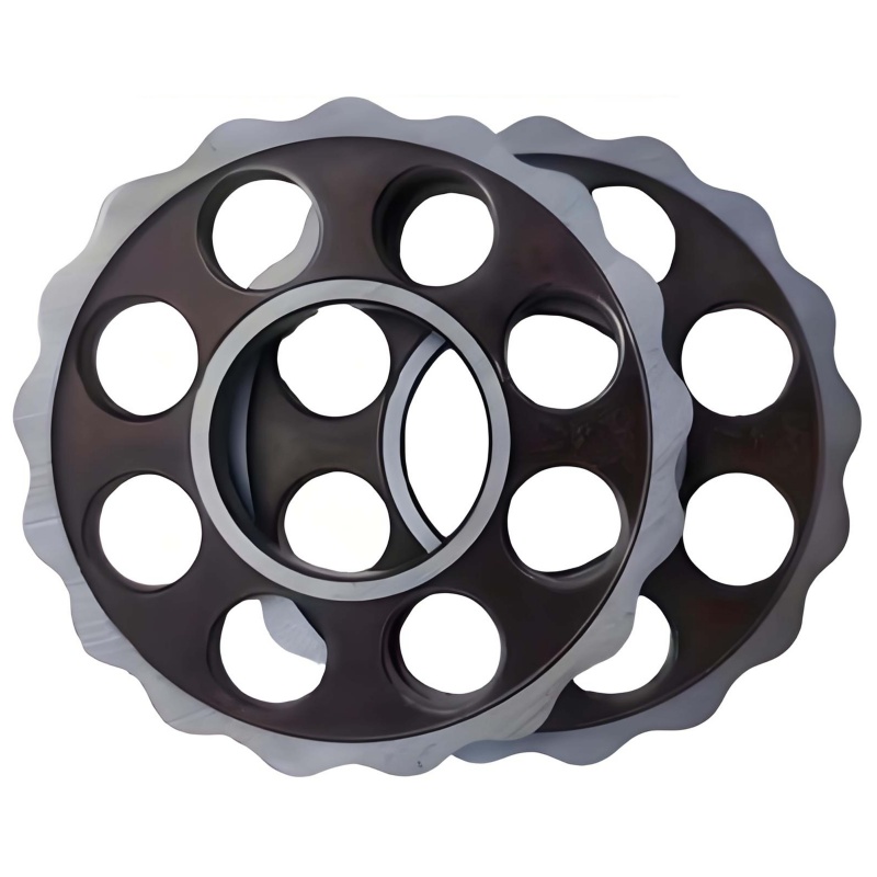
| Joint actuators | Actuator housings, motor end caps, stator seats, rotor spacers, bearing seats | 5-axis milling, turn-mill | 6061/7075 Al, brass | Bore ±0.005–0.01 mm, concentricity 0.005 mm |
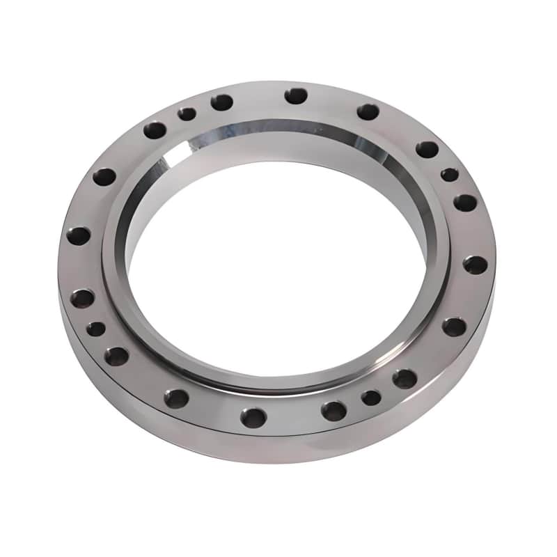
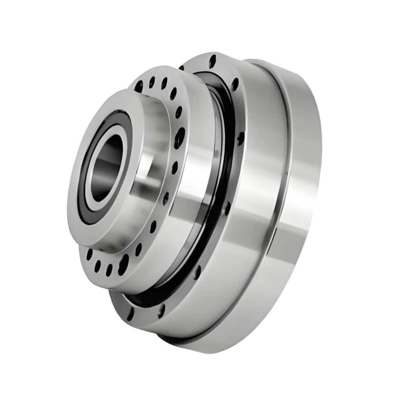
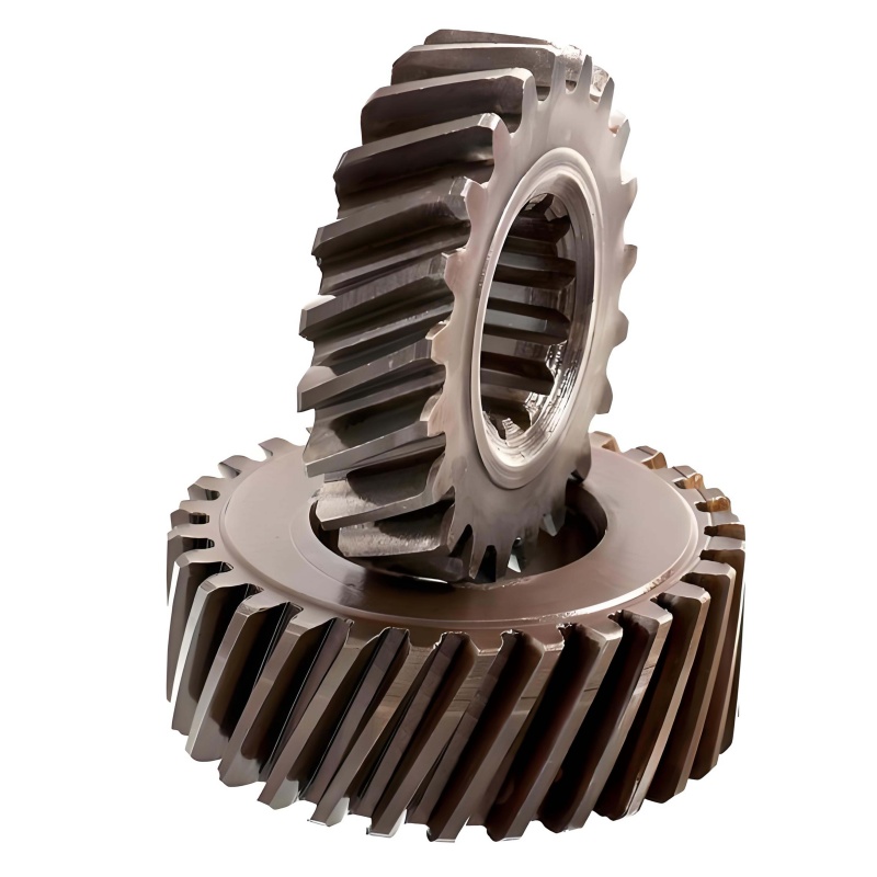
| Reducers / transmission | Harmonic (strain-wave) housings, output flanges, gear blanks, coupling sleeves, pulleys | Turning + milling, grinding on request | 7075 Al, 17-4 PH, 440C, bearing steel | IT6–IT7 on mating features |
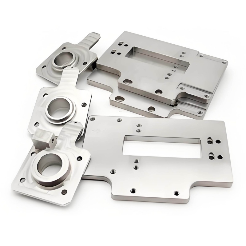
| Structural skeleton | Thigh/shank links, pelvis plates, shoulder and elbow brackets, rib frames, spine segments | 3-/4-/5-axis milling | 7075-T6, Ti-6Al-4V, carbon-fiber plates with metal inserts | Positioning ±0.02 mm, flatness per drawing |
| Wrist / ankle / foot | Ankle joint housings, wrist yokes, foot sole plates, damping mounts | 5-axis milling, turn-mill | 7075 Al, titanium, 304 SS | Critical axes ±0.01 mm |
| Drivetrain | Drive shafts, lead screws, ball-screw shafts, shaft couplers, lock nuts | CNC turning, Swiss-type, turn-mill | 303/316 SS, S45C, bearing steel, titanium | Diameter IT6, Ra 0.4–0.8 on sealing surfaces |
| Sensor integration | Encoder brackets, IMU mounts, torque-sensor flexure frames, lidar/camera housings | Milling, micro-milling | 6061 Al, PEEK, POM, titanium | Flatness and parallelism 0.01 mm |
| Dexterous hands | Finger phalanges, palm plates, tendon guide pulleys, miniature joint seats | 5-axis, Swiss turning | 7075 Al, titanium, PEEK, Delrin | Features down to ~0.5 mm wall |
| Thermal & cable | Motor heat sinks, cable-routing brackets, covers, connector shells | Milling | 6061 Al, copper, brass | Per print |
| R&D tooling | Assembly jigs, test fixtures, calibration blocks, life-test rig parts | Milling, grinding | MIC-6 plate, 6061, tool steel | Fixture-grade precision |
If a part is not on this list, that does not mean we cannot make it — humanoid robot designs are highly individual, and roughly a third of the parts we produce for robotics customers are geometries we have never seen before. Send the model and we will tell you exactly how we would machine it.
3. Materials for CNC machined robot parts: a practical guide
Material choice in robotics is almost always a trade between strength, weight, cost, and machinability. These are the alloys and engineering plastics we run most often, and where each one earns its place.
Aluminum alloys — the default for structural robot parts
- 6061-T6: The workhorse. Good strength, excellent machinability, anodizes cleanly, and costs the least. Used for general brackets, housings, covers, and heat sinks.
- 7075-T6: Significantly stronger at the same weight; the standard choice for load-bearing frames, joint housings, and leg links where 6061 would flex. It is slightly harder on tooling and costs more, but the weight savings on a humanoid limb are usually worth it.
- 2024-T3 / 5052: Used where fatigue behavior or forming history matters; MIC-6 cast tooling plate is our default for flat fixtures and inspection jigs that must stay dimensionally stable.
Titanium — when strength-to-weight is non-negotiable
- Ti-6Al-4V (Grade 5) offers the best strength-to-weight ratio of any common structural metal, with outstanding fatigue and corrosion resistance. We machine it for highly loaded joint pins, ankle and hip components, fasteners, and parts where a 7075 equivalent would be too bulky. Titanium costs more in both stock and cycle time, so we help customers use it only where the load path justifies it — and we are comfortable running it in single-piece prototype quantities.
Stainless and high-strength steels
- 303 / 304 / 316: Shafts, spacers, and corrosion-exposed fasteners; 303 is the free-machining grade, 316 for any outdoor or chemically exposed use.
- 17-4 PH (typically H900): Age-hardened, very strong and still machinable — a frequent choice for reducer output flanges and high-load coupling parts.
- 440C / bearing steels (GCr15, S45C hardened): Wear surfaces, shafts and gear blanks, with cylindrical grinding available when roundness and surface finish are critical.
Brass and copper — conductive seats, motor commutator-related parts, heat-spreading components, and RF/sensor housings that need shielding.
Engineering plastics — PEEK for stiff, light, temperature-resistant sensor holders and insulating bushings; Delrin/POM for low-friction guide parts and pulley sheaves; UHMW-PE and Torlon for wear and impact duties. Plastic parts are machined with sharp tooling and controlled feeds to avoid burrs and internal stress, and we hold metal-to-plastic fit clearances on the drawing rather than guessing.
Every production batch ships with mill certificates on request (EN 10204 3.1), so you always know what alloy is actually inside your robot.
4. Our CNC capabilities for robotics work
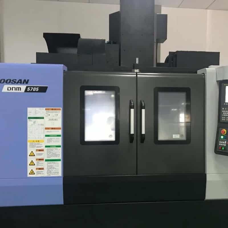
Multi-axis milling. 3-axis work covers plates, covers and straightforward brackets; 4-axis indexing handles bolt circles and parts machined around an axis; simultaneous 5-axis CNC machining is what makes complex robot joint housings, wrist yokes and ankle forks economical — the part reaches near-net shape in one or two setups instead of five, which directly improves the positional relationship between the bores that define a joint’s rotation axis.
Turning and turn-mill. Motor shafts, reducer sleeves, flanged housings and pulleys are cut on CNC lathes and turn-mill centers, with milling, cross-drilling and engraving done in the same clamping. For shaft-type parts under ~32 mm diameter with tight length-to-diameter ratios, Swiss-type turning keeps deflection under control — important for the small, long drive screws and tendon parts found in dexterous hands.
Realistic tolerances. General features are made to ISO 2768-mK unless the drawing says otherwise. Critical mating geometry — bearing bores, shaft diameters, reducer register diameters — is routinely held at IT6–IT7, i.e. ±0.005 mm to ±0.01 mm depending on nominal size, with concentricity, perpendicularity and parallelism controlled per your GD&T. We will flag a tolerance that is tighter than the feature actually needs, because over-specifying non-critical surfaces is the fastest way to inflate the price of a humanoid robot component for no functional gain.
Thin walls and light-weighting. Pocketed structural parts with 0.8–1.0 mm floors/walls are routine; down to ~0.5 mm is achievable with careful fixturing and climb-finishing strategies. Rib layouts, pocket radii and corner reliefs are exactly the kind of detail our DFM feedback addresses before metal is cut.
Surface treatments, managed end to end.
表格
| Finish | Where it is used in robotics |
|---|---|
| Bead blasting / brushing | Uniform cosmetic look on housings and covers |
| Anodizing Type II (color) | Corrosion protection and color coding of joint modules |
| Hard anodizing Type III | Wear-resistant bores and sliding surfaces; note the 5–20 µm layer build-up, which we compensate in the machining dimensions |
| Chem film / Alodine | Electrical continuity with corrosion protection on grounded parts |
| Passivation / electropolish | Clean stainless shafts and medical-grade-style finishes |
| Black oxide, nickel/zinc plating, PVD | Steel fasteners, shafts and cosmetic dark parts |
| Laser-engraved part number + revision + serial | Full traceability on every batch |
5. Quality control: how precision robot parts are actually verified
A tight tolerance on paper means nothing without evidence. Our standard flow for robotics orders:
- Incoming: alloy verification against mill certificates; bar stock separated and labeled by heat number.
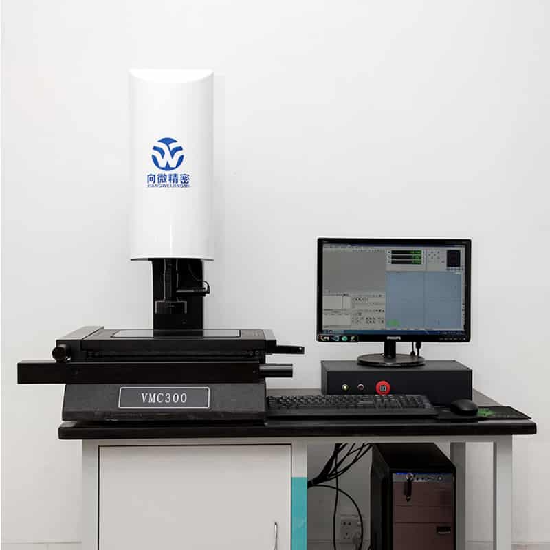
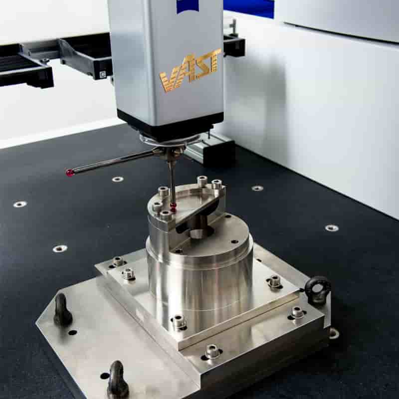
- First article: full dimensional report on the first approved part — CMM for 3D geometry and GD&T, micrometers/bore gauges for diameters, surface-roughness tester for sealing and bearing surfaces, hardness tester after heat treatment. AS9102-style FAI or inspection checklists in your format are available.
- In-process: operators check critical dimensions after each operation; for small robotics batches, the critical features listed on the drawing receive 100% verification rather than sampling.
- Post-finish: parts are re-checked after anodizing/plating, because surface treatment changes dimensions slightly — this is where shops that don’t understand precision assemblies get into trouble.
- Packing: individual protective bags, foam separation for cosmetic faces, clear labels with part number/revision/quantity, and the inspection report packed with the shipment.
We work to ISO 9001 discipline, and materials are RoHS/REACH compliant on request. NDAs are standard — your drawings and robot design never become anyone else’s quotation reference.
6. From one-off prototype to low-volume production
Robotics programs move through predictable stages, and our process is built around all of them:
- Prototype (1–10 pcs). Send a STEP model; you receive DFM feedback and a quotation within 24 hours, parts in roughly 5–9 working days, expedited to 3–5 days when a demo deadline is immovable.
- Design iteration (rev B, C, D…). We retain CAM programs, fixturing notes and inspection records by part number, so a revised humanoid robot component is quoted against real history — and we call out when a design change affects a mating part you may have forgotten.
- Bridge / low-volume production (20–500 pcs). Soft tooling and optimized fixturing bring unit cost down while preserving flexibility for the engineering changes that are still normal at this stage.
- Series production (500–5,000+ pcs per batch). Dedicated fixtures, SPC on key characteristics, agreed raw-material safety stock, and blanket-order / partial-delivery scheduling so component flow matches your assembly plan instead of tying up your cash in inventory.
This prototype-to-production continuity matters: a shop that only makes one-off prototypes often cannot hold batch consistency, while a high-volume house typically refuses the fast design changes a humanoid robot program lives on. We sit deliberately in the middle.
7. Why robotics companies choose us as their custom CNC machining partner
- Non-standard customization is our entire business. No catalog, no “similar part substitution.” Your print is the spec.
- Real engineering feedback before cutting. Tool-access problems, internal corner radii, wall thickness, anodize build-up, assembly stack-up — we raise issues at quotation stage, not after delivery.
- One vendor, full process coverage. Milled parts, turned shafts, sheet-metal brackets, and every common finish coordinated under one PO, with one contact accountable for the whole shipment.
- Difficult materials in small quantities. Titanium, 17-4 PH and PEEK at prototype quantity — no minimums designed to push you toward easy metals.
- Export experience. We routinely ship precision machined parts to customers in Europe, North America, Russia, Pakistan, South Africa and elsewhere, with correct HS codes, commercial invoices, and DAP/DDP handling so customs is not your problem.
- Communication in English on engineering terms. Drawings, GD&T, material tempers and finish specs are read literally; questions come back before machining, never after.
8. How to request a quote (and get a fast, accurate answer)
To quote a custom CNC machined robotics or humanoid robot component, send:
- 3D model: STEP / IGES / X_T (native SolidWorks/Creo/Fusion files also fine).
- 2D drawing in PDF, with critical tolerances and GD&T marked, plus general tolerance standard.
- Quantity per order and estimated annual usage.
- Material and any certificate requirements (e.g., 3.1 cert, RoHS).
- Surface finish and color (e.g., 7075, hard anodize black, Ra 1.6 max).
- Needed-by date, and any shipping/Incoterms preference.
- If convenient, a sentence on how the part assembles — it often lets us catch an interference issue you would rather find from us than from a prototype.
Quotations come back within 24 hours with process notes, material lead time and an honest delivery date.
9. FAQ
What is custom CNC machining for robotics? It means manufacturing robot-specific metal or plastic parts directly from a customer’s CAD model using CNC milling, turning and multi-axis machining, rather than selecting standard catalog components. It is the standard way to produce precise, lightweight, load-bearing parts for robots and humanoid robots.
Which humanoid robot components are typically CNC machined instead of 3D printed, stamped or cast? CNC is the default for anything that carries load, mates with bearings or gears, or needs tight dimensional control: joint housings, reducer flanges, structural links, shafts, sensor mounts and dexterous-hand parts. 3D printing suits early form prototypes; stamping suits simple high-volume sheet parts; casting suits large volumes after geometry is frozen. Most humanoid programs combine all four, with CNC carrying the precision-critical portion.
Do you have a minimum order quantity? No. One-piece prototypes are normal for R&D customers, and pricing is tiered from 1 pc to series volumes.
How tight a tolerance can you hold on robot joint parts? General features follow ISO 2768-mK; bearing bores and shaft seats are routinely held at IT6–IT7, around ±0.005–0.01 mm depending on size, verified on a CMM with a report. Feasibility for anything tighter is confirmed against the specific geometry before we commit.
How do you guarantee consistency between prototype and later production batches? Part programs, setup sheets, fixture records and first-article results are archived by part number and revision; material heat numbers are traceable; and critical characteristics follow the same inspection method at every batch. When a drawing revision changes a dimension, the change history is explicit on the inspection report.
What are typical lead times? Prototypes: 5–9 working days, 3–5 days expedited. Low-volume production: generally 2–4 weeks depending on material and finish. Firm dates are stated on every quotation instead of “about two weeks.”
Will you sign an NDA? Yes, mutual NDAs are signed routinely before model files are shared.
10. Let’s build your next robot part
If you are designing a humanoid robot, an industrial automation cell, a mobile platform or a research manipulator, your custom CNC machined components deserve a shop that reads drawings like an engineer and delivers like a production partner. Send your STEP files and drawings for a free DFM review and a 24-hour quotation — and let’s see how light, stiff, and precise your next humanoid robot component can be.